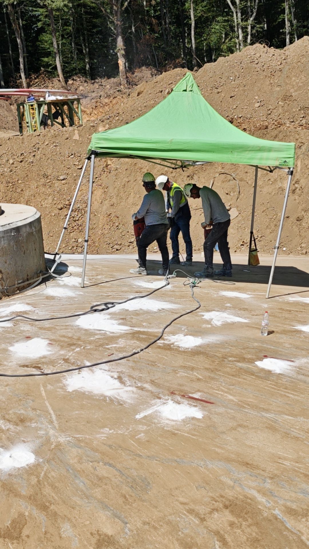
Epoxy and Cement Injection in Wind Turbines
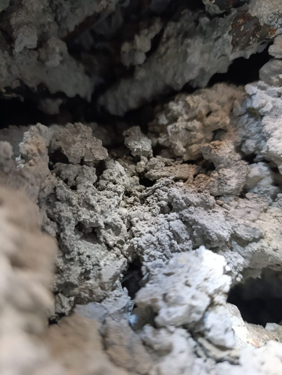
Epoxy and cement (grout) injection applications in wind turbine foundations are distinguished from each other due to their mechanical functions. Epoxy injection is used to repair capillary and structural cracks in the concrete, restoring its monolithic (single-piece) load-bearing property. Cement (grout) injection, on the other hand, is applied to fill the large voids between the tower flange and the reinforced concrete foundation, ensure load transfer, and increase fatigue resistance.
For both systems to be successful, the sequence of operations must be strictly followed.
1. Epoxy Injection Stages (Structural Crack Repair)
It is the process of filling capillary cracks (typically between 0.1 mm and 5 mm) with high-adhesion and high-tensile-strength resins.
-
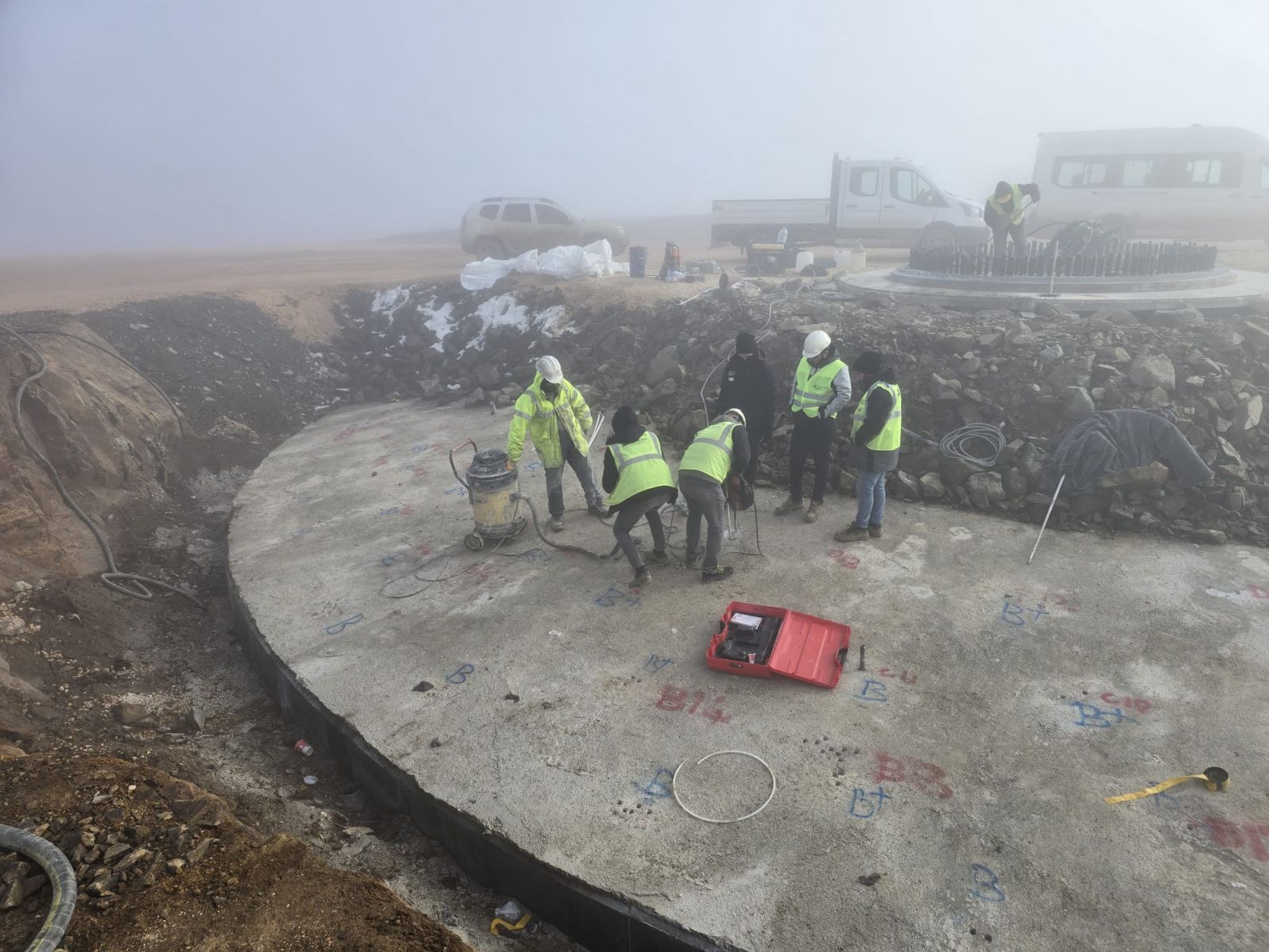
1.1. Surface Preparation and Detection: Determining crack boundaries and cleaning.
The crack line on the concrete surface is cleaned using a grinder. To prevent dust or dirt from filling the crack, compressed air is applied to open the capillary voids. It must be ensured that the surface is completely dry (moisture breaks the adhesion of the epoxy).
-
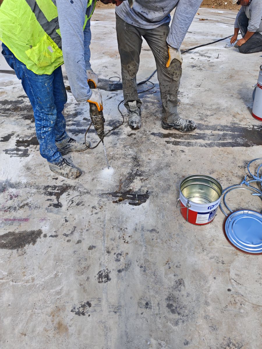
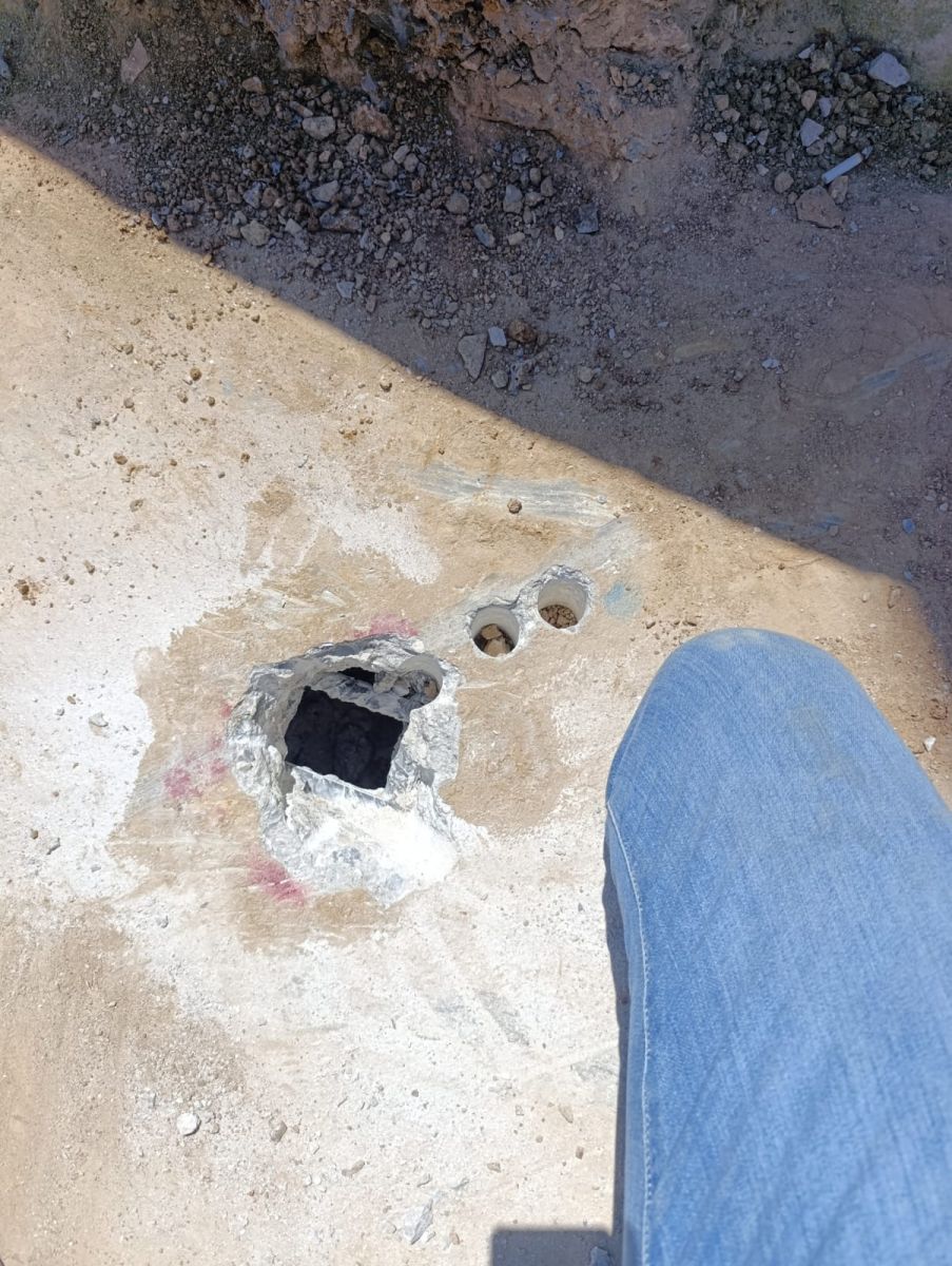
1.2. Packer (Dowel) Placement: Installation of injection packers.
Depending on the crack width and depth, holes are generally drilled at specified intervals along the crack. Injection packers, through which the epoxy resin will be pumped, are inserted into these drilled holes and tightened.
-
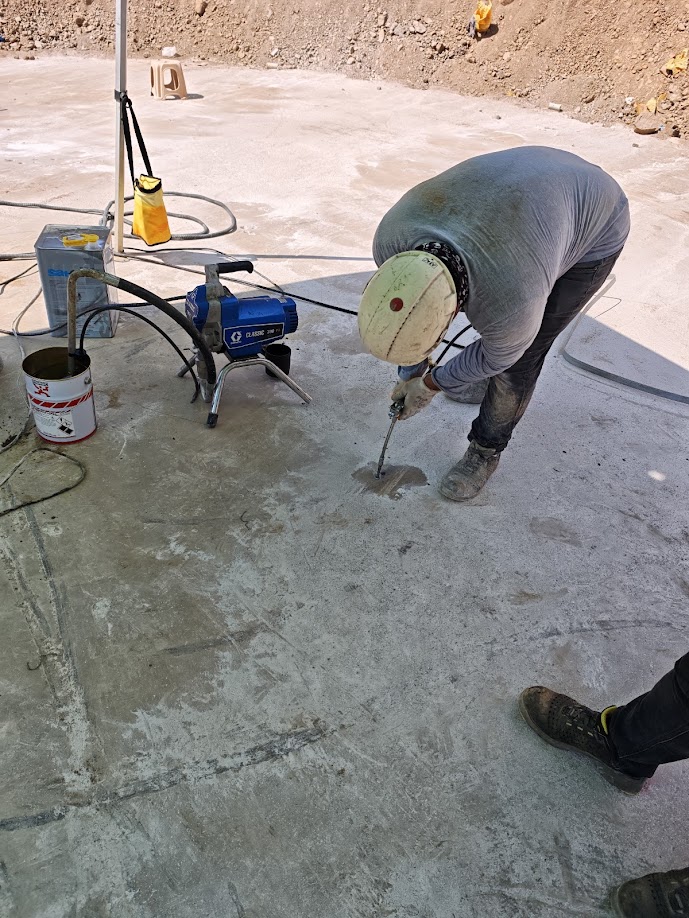
1.3. Injection Process: Bottom-to-top low-pressure filling.
Once the sealing mortar has cured, low-viscosity (water-consistency) structural epoxy resin is pumped from the lowest packer using a pressure pump. Pumping continues until the resin flows out of the packer immediately above it. When resin emerges from the upper packer, the lower packer is closed, the pump is connected to the upper packer, and the process is completed sequentially.
-
1.4. Curing and Cleaning: Preparing the surface for delivery.
The epoxy resin is left to cure for the duration specified in its technical data sheet. Once curing is complete, the packers on the surface are broken off and removed, and the surface is cleaned.
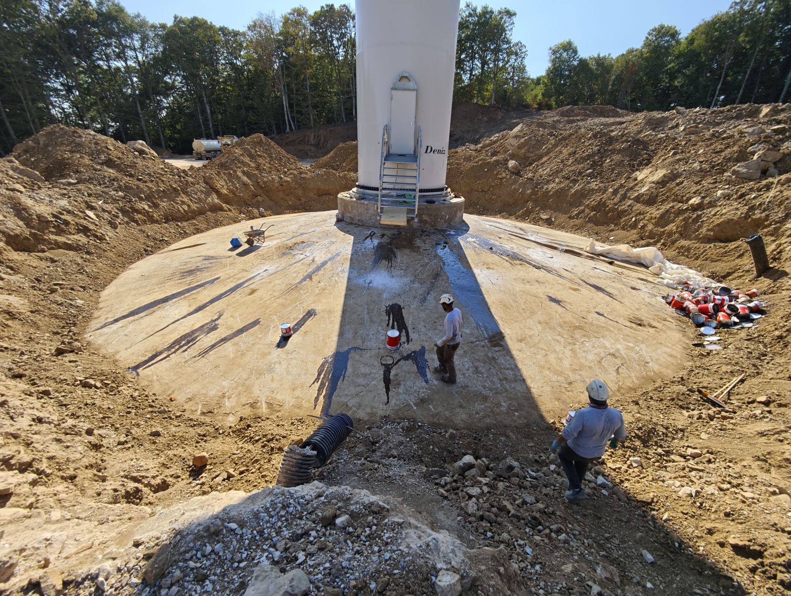
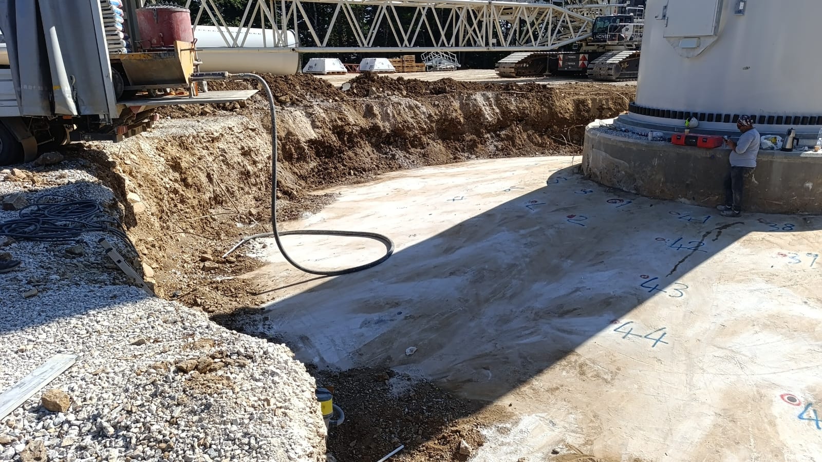
2. Cement / Grout Injection Stages (Flange - Foundation Connection)
It is the pouring/injection process used in wind turbines that accommodates dynamic loads, typically utilizing high-strength (non-shrink) cement-based mortars.
-
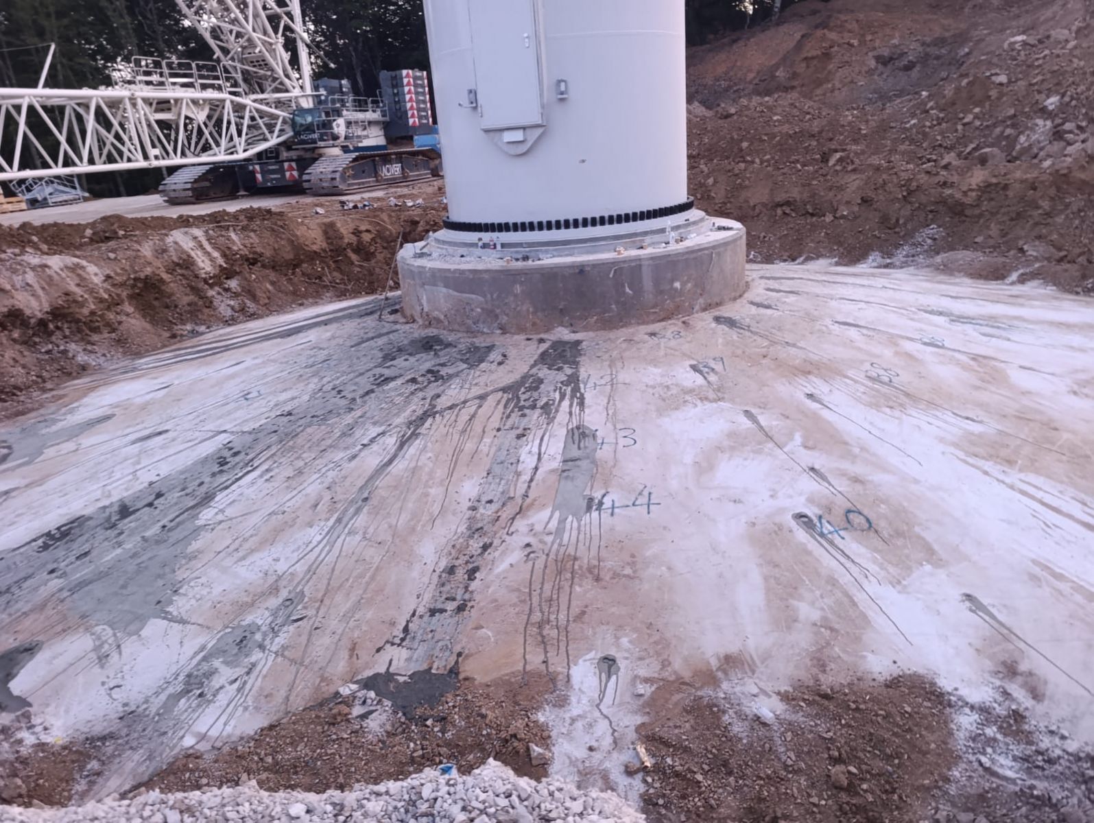
2.1. Formwork Installation (Headbox): Design to create hydrostatic pressure.
A leak-proof system is installed around the flange. To allow the grout to fill all voids under its own weight, a funnel/height (headbox) is provided on the pouring side so the grout can build pressure.
-
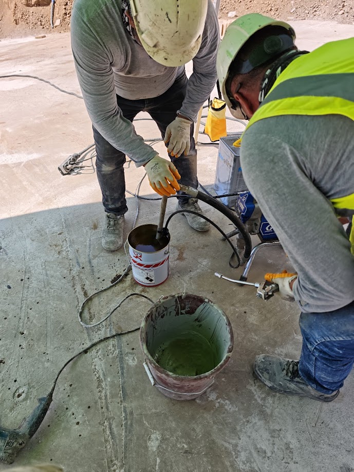
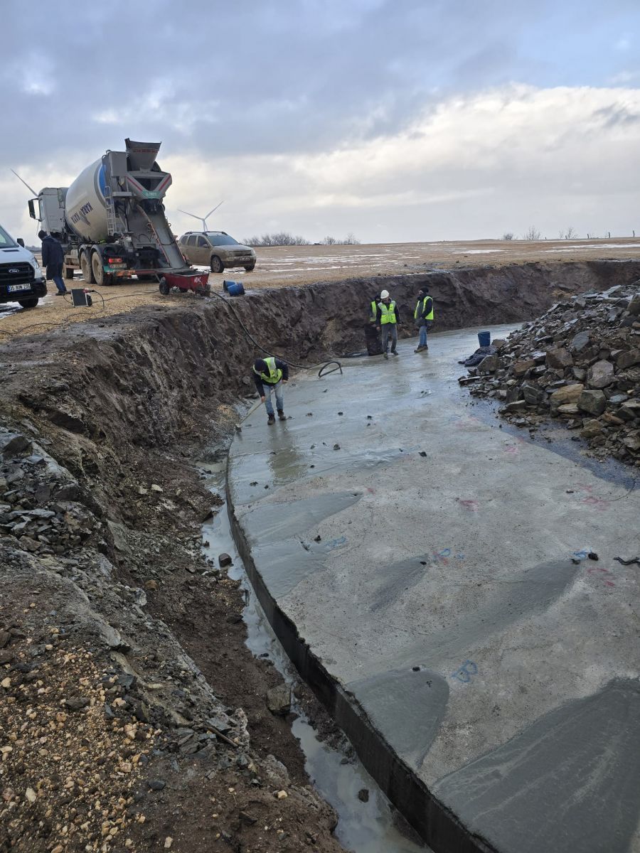
2.2. Mixing the Mortar: Ideal water/cement ratio.
A high-strength (e.g., 100+ MPa) cement-based grout mortar is mixed using a mechanical mixer at the precise water ratio specified by the manufacturer until it becomes lump-free and fluid. Mixer speed and duration are of critical importance to avoid trapping air within the mortar.
-
2.3. Continuous Pouring Process: Preventing air entrapment.
The prepared grout mortar is poured/pumped continuously from only one side of the formwork. The process continues until the grout is seen coming out from the opposite side. Pouring from both sides is strictly prohibited as it will cause air voids to be trapped inside. Vibrators are not used; if necessary, light guidance can be provided with steel strips to help the mortar self-consolidate.
Address: Fahrettin Altay Mh. 65/13 Sk. No:31/1 Karabağlar / İzmir
Phone: +90 232 278 10 50
info@atakkompozit.com
Copyright © 2024 | All rights reserved.
iz ajans